- Network management and monitoring

Getty Images/iStockphoto

How to perform VLAN troubleshooting
Common VLAN issues include physical connectivity problems, duplex mismatches, forwarding loops, unicast flooding and Layer 3 configuration errors. These troubleshooting steps can help.

- Terry Slattery, NetCraftsmen
Virtual LAN, or VLAN , technology can fail for various reasons. VLAN connectivity problems can occur due to physical connections, improper Layer 2 data link configuration errors or problems with the Layer 3 routed network configuration.
Here are some steps to take when troubleshooting VLAN connectivity issues.
Physical connectivity
Basic physical connectivity must exist for the network to function. Typical problems include broken wires or optical cables, dust or dirt on optical connectors, bad connectors, interference from electrical systems or pinched cables.
Many of these problems manifest themselves as unidirectional links, where packets go in one direction but not the other. Network devices can frequently detect unidirectional links, making it easier to diagnose with simple commands, like show interface . Admins need to check the interface status and error counters in the output to identify the specific type of problem.
Duplex mismatch
On slow-speed Ethernet links, check the duplex setting . Both sides of a link must be configured for the same duplex setting -- auto, full or half -- and speed. A duplex mismatch can work at low packet rates and fails at higher packet rates, so don't rely on a simple ping test. An interface that shows late collisions is in half-duplex communicating with a full-duplex interface. A full-duplex interface shows runt frames if the connected device is in half-duplex. The recommended setting for most devices is auto.
Incorrect VLAN configuration
The most common data link errors are incorrect configuration of a port's VLAN ID or omitting the voice VLAN ID on ports that connect IP phones. The link looks good, and packet counters increment. But there's no connectivity. In this case, admins should run a simple check of the configuration.
On trunking links, admins need to set the native VLAN, which tells the switch which VLAN to use for any frame that doesn't carry a VLAN ID. This ID is normally consistent across the entire network, and admins need only perform a simple configuration check.
Switch-to-switch links often use trunking to pass multiple VLANs over a single link. The permitted VLAN list must match on both ends of the link. A mismatch can result in isolated instances of a VLAN. Connectivity works for some endpoints and not for others. Here, run simple configuration checks on the switch trunk interfaces.
The above configuration checks are ideal places to apply configuration validation automation . These checks don't need to apply changes -- they simply need to highlight potential problems to the networking staff.
Forwarding loops in a switched network
Switched networks traditionally rely on Spanning Tree Protocol (STP) to prevent forwarding loops. But, in some cases, loops occur even with STP to prevent them. A loop rapidly forwards Ethernet frames around the loop, consuming interface bandwidth and switch CPUs. It quickly causes a network to become so congested it ceases to function. Unfortunately, because the CPUs and network links are saturated, it is impossible to use the network to diagnose the problem.
To troubleshoot, admins should break the network into successively smaller domains to identify the loop's location. Divide the network in the middle, and identify which half contains the loop. Admins can repeat the subdivision process until they identify the switches on which the loop is located and the interfaces that are interconnected. It's a good idea to practice this in a lab environment to learn the process. Vendors have also created functions, such as Unidirectional Link Detection, Loop Guard, Root Guard and BPDU Guard, to prevent different types of loops.
Unicast flooding
In rarer cases, a switch might forget where an endpoint is located within a VLAN, resulting in a situation known as unicast flooding . This happens when the switch's media access control address-to-port cache timer is different than the VLAN's router IP address-to-MAC address cache. (An example is described in " Unicast Flooding in Switched Campus Networks " ). The switch forgets which port a given MAC address is on, causing the switch to flood any frame destined for the MAC address to all ports in the VLAN. Several network topologies and scenarios can cause this flooding. If the affected systems send a lot of data, like doing a disk backup, all systems on the VLAN will experience a large load.
Admins can identify this problem when the end systems on the affected VLAN become sluggish and the packet counters on all interfaces in the VLAN increment at the same rate. One option is to set the MAC address-to-port timer slightly higher than the IP address-to-MAC timer. Alternatively, switch vendors have implemented features that help avoid the high load by limiting the number of unknown unicast flooding operations. These are vendor-specific commands, so admins should check with their provider.
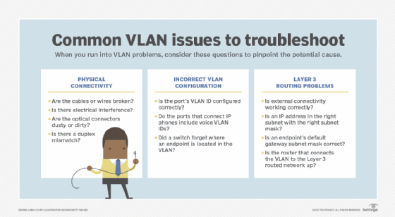
Layer 3 (routed network) problems
Another class of problems affects a VLAN's connectivity to the rest of a Layer 3 network. In these cases, the VLAN operates correctly, but its external connectivity doesn't work. If admins can ping at least one other system on the subnet, basic Layer 2 connectivity is working, and it's likely a Layer 3 problem. There are exceptions, so be open to alternative scenarios.
Endpoint configuration
If the problem is with a single endpoint, check that its IP address is in the right subnet and has the right subnet mask . An incorrect configuration could result from a typo in the configuration process or a wrong VLAN ID configuration on the endpoint's switch interface, which puts it in the wrong VLAN/subnet.
Observe the symptoms, and determine if the problem is at the physical layer, data link layer, routed layer or application layer.
Gateway configuration
Admins should be able to ping the default gateway on the subnet, as well as adjacent systems on the same subnet. If adjacent systems respond to ping but the default gateway doesn't, then two possible scenarios are causing the issue.
The first option is the default gateway isn't properly configured. This could be a missing switch virtual interface (SVI), or the router that connects the VLAN to the Layer 3 routed network is missing, misconfigured or not in an "up" operational state. Admins should diagnose the SVI or router connection next and, when it is validated, go back to the failing endpoint. Further testing may require admins to return to the Layer 2 testing scenarios described above.
The second possibility is the endpoint's default gateway subnet mask is wrong. The symptom of this scenario is the endpoint can ping some, but not all, other endpoints within the VLAN/subnet. Whether it can reach the default gateway and have packets properly routed back depends on the specific addresses involved. Again, this is a case where network validation automation is a great help.
Network troubleshooting is always best using a divide-and-conquer approach. Observe the symptoms, and determine if the problem is at the physical layer, data link layer, routed layer or application layer. Determine where connectivity fails and why, and then start checking specific items related to that layer. Test for each potential failure to identify where the problem lies, and identify what needs to be corrected. VLAN troubleshooting is a valuable skill learned through experience.
Dig Deeper on Network management and monitoring

How to set up a VLAN for enterprise networks

VLAN vs. subnet: What's the difference?

Managed vs. unmanaged switches: What are the differences?

Why network configuration templates are useful in automation

Part of: A guide to virtual LANs
While VLANs are a type of subnet, they have their own unique capabilities and characteristics that differentiate them from subnets. However, the OSI model plays a major role in both.
VPNs and VLANs are different technologies with some similarities. VPNs connect authorized users to corporate network resources, while VLANs connect geographically separate devices.
VLANs offer security and traffic management benefits but have limitations in routing and scale. VXLANs address those challenges by creating a Layer 3 network overlay.
VLANs can secure and prioritize network traffic. To set up VLANs correctly, teams should understand concepts like VLAN tagging and subnets.
Virtual LANs can help homeowners segment their network traffic for enhanced control and security. Network analyst John Fruehe takes you inside his home VLANs.
Microsoft 365 Copilot, an AI assistant, offers several promising features. Find out how to configure Copilot with Teams workflows...
With its AI capabilities, Microsoft Copilot provides several enhancements to Microsoft Teams functionality, including meeting ...
Organizations have ramped up their use of communications platform as a service and APIs to expand communication channels between ...
Auditing is a crucial part of mobile device security, but IT admins must ensure their approach is thorough and consistent. Learn ...
With the right software, almost any mobile device can be a payment terminal. Learn about the mobile point-of-sale options beyond ...
To keep corporate and user data safe, IT must continuously ensure mobile app security. Mobile application security audits are a ...
Rocky Linux and AlmaLinux are new distributions created after Red Hat announced the discontinuation of CentOS. These ...
The Broadcom CEO says public cloud migration trauma can be cured by private cloud services like those from VMware, but VMware ...
New capabilities for VMware VCF can import and manage existing VMware services through a single console interface for a private ...
Popular pricing models for managed service providers include monitoring only, per device, per user, all-you-can-eat or ...
Global IT consultancies take a multilayered approach to GenAI training by developing in-house programs, partnering with tech ...
IT service providers are upskilling a large portion of their workforces on the emerging technology. The campaign seeks to boost ...
Troubleshooting VLAN Issues in Network: A Comprehensive Guide
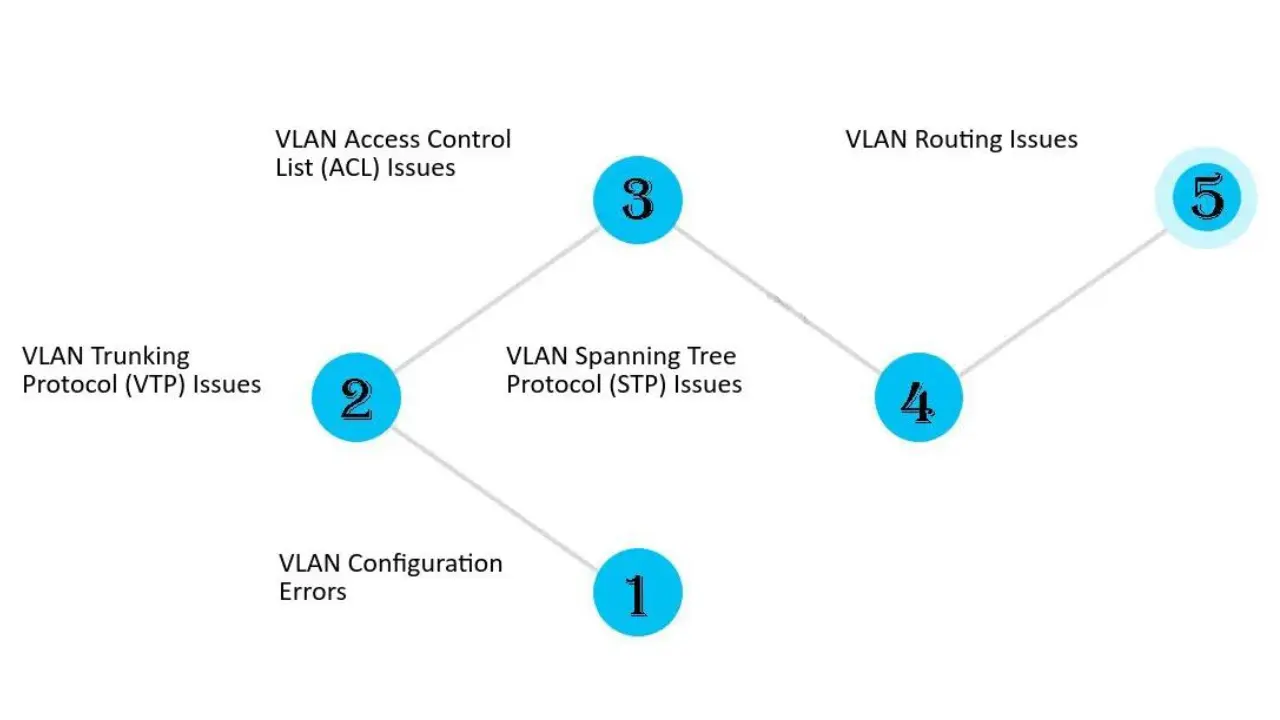
In today’s interconnected world, networks play a crucial role in ensuring seamless communication and data transfer. However, network VLAN issues can disrupt this flow, leading to connectivity problems, performance degradation, and even security breaches. VLANs, or virtual local area networks, are logical groupings of devices that share the same broadcast domain. While VLANs offer numerous benefits, such as network segmentation, improved efficiency, and enhanced security, they require proper configuration and maintenance to function optimally. In this comprehensive guide, we will explore the steps to troubleshoot VLAN issues in a network using common network troubleshooting tools.
Table of Contents
Understanding VLANs
Before diving into troubleshooting techniques, it’s essential to have a clear understanding of VLANs and their role in network architecture. VLANs allow network administrators to partition a physical network into multiple logical networks, each with its own separate broadcast domain. By doing so, VLANs enable the isolation of network traffic, enhancing security and improving network performance.
Each VLAN is assigned a unique identifier, known as a VLAN ID or VID. Devices within the same VLAN can communicate with each other directly, while traffic between different VLANs requires routing through a Layer 3 device, such as a router or Layer 3 switch. This logical separation allows for more efficient network management and reduces the risk of unauthorized access to sensitive data.
Common VLAN Issues
VLANs, like any other network component, can experience issues that hinder their functionality. Some of the common VLAN issues include:
1. VLAN Connectivity Problems
Connectivity problems can arise when devices within a VLAN are unable to communicate with each other or with devices in other VLANs. This can result from misconfigured VLAN trunks, incorrect VLAN assignments, or issues with the network switch.
To troubleshoot VLAN connectivity problems, network administrators can perform the following steps:
- Check VLAN configurations on the switch and ensure the correct VLANs are assigned to the appropriate ports.
- Verify that VLAN trunks are properly configured and allow the necessary VLANs to pass traffic.
- Use network monitoring tools to identify any network loops or excessive broadcast traffic that may be impacting connectivity.
- Test connectivity between devices within the VLAN and between VLANs to pinpoint the source of the issue.
2. VLAN Performance Degradation
VLAN performance degradation can manifest as slow network speeds, high latency, or intermittent connectivity issues. Multiple factors, such as inadequate bandwidth, network congestion, or misconfigured Quality of Service (QoS) settings, can contribute to this issue.
To address VLAN performance degradation, network administrators can take the following steps:
- Evaluate the available bandwidth and ensure it is sufficient for the traffic volume within the VLAN.
- Identify any network bottlenecks or congestion points that may be causing performance issues.
- Configure QoS settings to prioritize critical traffic and minimize the impact of non-essential traffic.
- Monitor network traffic and analyze performance metrics to identify patterns or anomalies that may be contributing to the degradation.
3. VLAN Security Breaches
Security breaches within VLANs can result in unauthorized access to sensitive data or malicious activities within the network. Common security issues include VLAN hopping, where an attacker gains unauthorized access to a VLAN, and VLAN misconfigurations that expose sensitive VLANs to unauthorized devices.
To enhance VLAN security and prevent breaches, network administrators should consider the following measures:
- Implement VLAN access control lists (ACLs) to restrict traffic between VLANs and enforce security policies.
- Enable port security features to prevent unauthorized devices from connecting to VLAN ports.
- Regularly update and patch network devices to address any security vulnerabilities.
- Monitor network logs and use intrusion detection systems to identify any suspicious activity within VLANs.
Troubleshooting VLAN Issues
When faced with VLAN issues, network administrators can leverage various network troubleshooting tools and techniques to pinpoint and resolve the problem. Here are some commonly used methods:
1. VLAN Tagging Verification
VLAN tagging is a method used to identify VLAN membership for network traffic. It involves adding a VLAN tag to Ethernet frames, indicating the VLAN to which the frame belongs. To verify VLAN tagging, administrators can use network traffic analysis tools, such as Wireshark, to capture and analyze network packets. By examining the VLAN tags within the packets, administrators can ensure that traffic is correctly tagged and assigned to the appropriate VLAN.
2. VLAN Configuration Review
Reviewing the VLAN configuration is crucial to identify any misconfigurations that may be causing issues. Administrators should check VLAN assignments, VLAN IDs, and port configurations on network switches or routers. Correct any identified discrepancies to ensure accurate assignment of devices to their designated VLANs.
3. Trunk Link Troubleshooting
Trunk links are used to carry traffic between switches and enable the passage of multiple VLANs. Issues with trunk links can lead to VLAN connectivity problems. Administrators should verify that trunk links are properly configured on both ends, allowing the necessary VLANs to pass through. Additionally, they should check for any issues with link aggregation protocols, such as EtherChannel or Link Aggregation Control Protocol (LACP), that may impact trunk link functionality.
4. Spanning Tree Protocol (STP) Analysis
The Spanning Tree Protocol (STP) ensures loop-free network topologies by preventing network loops. However, misconfigured or malfunctioning STP settings can cause VLAN connectivity issues. Administrators should analyze STP configurations and check for any inconsistencies or errors that may affect VLAN communication. Network monitoring tools, such as SolarWinds Network Performance Monitor, can assist in monitoring STP states and identifying potential issues.
5. VLAN ACL Review
VLAN access control lists (ACLs) provide an additional layer of security by restricting traffic between VLANs. If issues with VLAN connectivity continue, administrators need to examine the VLAN ACL configurations to confirm the approval of desired traffic and the prevention of unauthorized traffic. Careful analysis of ACL rules and their corresponding actions can help identify any misconfigurations or conflicting rules.
6. Device Firmware and Software Updates
Outdated firmware or software versions on network devices can introduce bugs or security vulnerabilities that may impact VLAN functionality. Administrators should regularly check for firmware or software updates provided by the device manufacturers and apply them accordingly. Keeping network devices up to date ensures optimal performance, bug fixes, and security enhancements.
7. Network Monitoring and Logging
Network monitoring tools play a vital role in identifying and troubleshooting VLAN issues. By monitoring network traffic, administrators can detect abnormal behavior, identify bottlenecks, and proactively address potential problems. Additionally, network logs provide valuable insights into network events and can assist in diagnosing VLAN issues when they occur.
Troubleshooting VLAN issues in a network requires a systematic approach and the use of appropriate network troubleshooting tools. By understanding VLANs, identifying common VLAN issues, and following the outlined troubleshooting steps, network administrators can efficiently resolve VLAN connectivity problems, performance degradation, and security breaches. Regular monitoring, configuration review, and firmware updates are essential to maintaining a robust and secure VLAN infrastructure. With these best practices in place, organizations can ensure a reliable and efficient network environment.
Related Posts
Importance of Internet Group Management Protocol

History of Data Communication Protocols
What is DNS? How Domain Name System works
Leave a reply cancel reply.
Your email address will not be published. Required fields are marked *
Save my name, email, and website in this browser for the next time I comment.
Troubleshooting Incorrect VLANs
The ability to segment the network provides clear advantages, such as increased security because devices can communicate only with other systems in the VLAN. Users can see only the systems in their VLAN segment. It can help control broadcast traffic and makes moving end systems around the network easier.
One of the keys to preventing VLAN assignment errors is to clearly document the VLAN arrangement. Should systems be moved, it is important to know how to reconnect them and forward them to the correct VLAN port.
In this tutorial:
Troubleshooting VLANs & Trunks
Lesson Contents
In a previous lesson I explained some of the possible interface issues that we can encounter. Once you verified that your interface(s) are configured correctly and you are still having issues, the problem might be related to VLANs & Trunks. Let’s take a look at some common issues and how to solve them.
VLAN assignment issues
Here is the topology:

H1 is unable to ping H2. There are no issues with the hosts, the problem is related to the switch. Let’s see what happens when we try a ping:
The two computers are unable to ping each other (what a surprise!). Let’s do a quick check if there are any interface errors:
The interfaces are looking good, no errors here. Let’s check the VLAN assignments:
At this moment it’s a good idea to check the VLAN information. You can use the show vlan command to quickly verify to which VLAN the interfaces belong. As you can see our interfaces are not in the same VLAN. Let’s fix this:
We’ll move interface Fa0/3 back to VLAN 1, both hosts are now in VLAN 1. Let’s try that ping again:
This solves our problem!
Lesson learned: Make sure the interface is in the correct VLAN.
Switchport mode issues
Time for another problem, same topology:
We verified that there are no interface errors, the interfaces are up and running:
The interfaces don’t show any errors. Let’s check the VLAN assignments:
Above you can see that FastEthernet 0/1 is in VLAN 10 but I don’t see FastEthernet 0/3 anywhere. Here are the possible causes:
- Something is wrong with the interface. We proved this wrong because it shows up/up so it seems to be active.
- The interface is not an access port but a trunk.
Let’s check the switchport information:
A quick look at the switchport information shows us what we need to know. We can confirm that interface fa0/3 is in trunk mode and the native VLAN is 1. This means that whenever H2 sends traffic and doesn’t use 802.1Q tagging that our traffic ends up in VLAN 1. Let’s turn this interface into access mode:
We’ll turn FastEthernet 0/3 into access mode and make sure it’s in VLAN 10. Let’s verify this:
Both interfaces are now active in VLAN 10. Checking the operational mode is also a good idea:
It now shows up as access mode. Let’s try that ping again:
Now I can send a ping from H1 to H2…problem solved!
Lesson learned: Make sure the interface is in the correct switchport mode (access or trunk mode).
VACL (VLAN Access-List) issues
Same two computers, same switch, different problem:
This scenario is a bit more interesting though. The computers are unable to ping each other so let’s walk through our list of “possible” errors:
We're Sorry, Full Content Access is for Members Only...
- Learn any CCNA, CCNP and CCIE R&S Topic . Explained As Simple As Possible.
- The Best Investment You’ve Ever Spent on Your Cisco Career!
- Full Access to our 795 Lessons . More Lessons Added Every Week!
- Content created by Rene Molenaar (CCIE #41726)
560 Sign Ups in the last 30 days

Forum Replies
Thanks alot Rene, these lessons are very helpful. Keep up the good work.
Hi Renee, With switchport trunk allowed vlan xx, do you have to specify this on both sides of the trunk link or is one side enough?
Regards, Hans de Roode.
Best to do it on both sides. Your switch(es) will complain when you receive traffic for VLANs that are not allowed on the trunk. It’s best practice to ensure that both ends of the trunk have the same configuration.
Hello Rene. Could you explain me what’s the difference between show ip interface brief and show interface fa0/x switchport? I’m asking this because you use first the show ip interface to check the status of a swichport (up/down) and the other to check operational mode. My question is why you don’t use only interface fa0/x switchport to get both information ( status and operatinal mode?
Hello Rodrigo
There are various ways to show the status of interfaces and each command provides different information and in different formats. The command initially chosen by Rene is the show ip interface brief will show the status and protocol of all the interfaces in a list, so you get a general picture of all interfaces with one command. If any of those interfaces are configured with IP addresses, those are also displayed.
The show interface fa0/x switchport command will show the switchport configuration of a single port in detail . This can be used when
10 more replies! Ask a question or join the discussion by visiting our Community Forum
- Articles Automation Career Cloud Containers Kubernetes Linux Programming Security
A sysadmin's guide to troubleshooting VLANs
%t min read | by Anthony Critelli (Sudoer)

All but the smallest networks are typically split into Virtual Local Area Networks (VLANs, for short), and understanding how to properly troubleshoot them can save you hours of back-and-forth with your network team. In the previous articles, I covered VLAN basics and configuration for Red Hat Enterprise Linux (RHEL) systems . Here, I’ll cover basic troubleshooting steps that you can use to rule out host problems before moving on to the network. By the end of this article, you’ll be able to confidently rule out problems with your servers.
Now that you know how to configure VLANs, I'll spend some time discussing how to troubleshoot them. If you’re working in a small shop where you handle both the servers and network devices, then this troubleshooting information can help to validate your server config before moving on to network devices. For larger organizations with a dedicated networking team, this process can help to prove that the server configuration is correct.
VLAN trouble can be difficult to isolate, since you may not have visibility into the upstream network devices that your servers plug into. However, some basic troubleshooting techniques can help to identify a possible VLAN issue so you can provide your networking team with as much information as possible for proper troubleshooting.
VLAN issues constitute a local area network problem. An obvious symptom is your local server being unable to reach other hosts on the same local network, such as your default gateway. Take a look at an example:
In the example above, you clearly can’t ping the default gateway. An ARP entry also isn’t populating for the host that you’re trying to ping, so there’s likely some kind of layer two issue, such as a VLAN configuration problem on the switch port (this possibility assumes that you’ve finished troubleshooting other aspects of the network, as discussed in our beginner’s article on network troubleshooting).
Troubleshooting this sort of issue with a packet capture can be instructive. Dig into the failure scenario above with tcpdump :
The above capture shows ARP traffic for a completely different subnet (192.168.2.X). This result is a dead giveaway that you have a VLAN misconfiguration on our hands. If the upstream switch port is on the wrong VLAN, you could be seeing traffic for an entirely different local area network.
If your interface configuration files look OK and you’ve performed the basic troubleshooting above, then it’s time to bring the issue to your network team. If the issue is with an access port and a single VLAN, then the upstream switch port may simply be on the wrong VLAN. If the issue is with a more complex trunk configuration, then there are a number of issues that could occur. The upstream switch port may not be configured with the correct VLANs, or the VLANs may not exist on the switch at all. Either way, these basic troubleshooting tools can help you to rule out your server and start looking at the network.
VLANs might seem complex to the network-uninitiated, but they’re just a simple way of dividing switches into multiple broadcast domains (and typically, IP subnets) for increased efficiency. Small networks may never move beyond a few VLANs, while complex data centers may have hundreds. In both cases, having a basic understanding of how to configure and troubleshoot VLANs can help you to more quickly isolate problems in your network and work toward the right resolution.
[Need more on networking? Download the Linux networking cheat sheet .]

Anthony Critelli
Anthony Critelli is a Linux systems engineer with interests in automation, containerization, tracing, and performance. He started his professional career as a network engineer and eventually made the switch to the Linux systems side of IT. He holds a B.S. and an M.S. More about me
Try Red Hat Enterprise Linux
Download it at no charge from the red hat developer program., related content.

You can access our entire course library with an All-Access Pass subscription

Advance Your Career with NSC's Comprehensive Online Training in Networking, Security, and Cloud Technologies.
- [email protected]
- +1 530 567 4539

- Networking Technologies

- Fri, 03 May 2024
VLAN Configurations: Setting and Troubleshooting
Virtual Local Area Networks (VLANs) are a fundamental technology in modern network management, allowing for the efficient segregation of networks without the need for additional physical hardware.
By effectively configuring VLANs, network administrators can enhance security, improve network performance, and ensure better resource management across the network infrastructure.
This blog delves into the critical concepts of native VLANs and VLAN mismatch issues , which are essential for maintaining network stability and security.
We will guide you through the processes of setting and changing VLAN configurations , address common troubleshooting scenarios, and explore the impact of trunk settings on network performance.
Understanding VLANs and Native VLAN Concepts
A Virtual Local Area Network (VLAN) is a technology that creates distinct broadcast domains within a single physical network. By partitioning a network into VLANs, organizations can control traffic within their networks, enforce security policies, and optimize the performance of their network resources. The key advantage of VLANs is their ability to provide segmentation at the data link layer, which allows for greater flexibility and efficiency in network design and management.
Exploring Native VLANs
The native VLAN serves a special purpose in network configurations, particularly in scenarios involving trunk ports. A trunk port on a switch can carry traffic for multiple VLANs, but the traffic from the native VLAN is not tagged with a VLAN identifier. This can simplify configurations but also introduces potential security risks if not properly managed. Understanding the native VLAN's role and ensuring it is correctly configured are crucial to maintaining network security and stability.
- Role and Configuration : Typically, the native VLAN is used as a default untagged VLAN on trunk ports. This setting allows devices on different VLANs to communicate via a single connection.
- Security Implications : Misconfigurations of the native VLAN can lead to security vulnerabilities, such as VLAN hopping attacks. It is important to ensure that the native VLAN is configured correctly and that unnecessary ports are not left in the default VLAN to mitigate potential risks.
Configuring VLANs on Cisco Devices
Configuring a new VLAN on Cisco devices is a straightforward process that can significantly enhance your network's organization and security. Here’s how you can set up a VLAN:
- Access the Switch Configuration : Log into your Cisco switch and enter the global configuration mode by typing configure terminal.
- Create the VLAN : Enter the command vlan [VLAN_ID] where [VLAN_ID] is the number you assign to your new VLAN.
- Name the VLAN : Assign a name to your VLAN for easier identification with name [VLAN_NAME].
- Assign Ports to the VLAN : Use the command interface [INTERFACE_ID], then switchport mode access, followed by switchport access vlan [VLAN_ID] to assign ports to your VLAN.
- Verify the Configuration : Always verify your settings with the show vlan brief command to ensure your VLAN is configured correctly.
Changing VLAN Settings
Changing existing VLAN configurations can help adapt your network to new requirements or improve its performance and security:
- Modify VLAN Assignment : To change the VLAN assignment of a port, first access the port configuration with interface [INTERFACE_ID].
- Reassign the VLAN : Use the command switchport access vlan [NEW_VLAN_ID] to move the port to a different VLAN.
- Verify Changes : It’s crucial to verify the changes with show vlan brief or show running-config to ensure the changes have been applied correctly.
Configuring and maintaining VLANs properly on your Cisco devices is essential for optimal network performance and security. By following these steps, you can ensure that your network is well-organized and secure.
For those interested in delving deeper into network troubleshooting techniques, particularly in complex scenarios involving Cisco devices, our Cisco ASA Firewall 9.x course offers extensive insights and practical guidance.
Troubleshooting VLAN Configurations
A native VLAN mismatch occurs when two connected devices are configured with different native VLANs on their trunk links. This can cause serious issues, including traffic black holes where frames are not properly routed. Here's how to diagnose and resolve native VLAN mismatches:
- Identify Symptoms : Look for symptoms such as intermittent connectivity issues or specific VLANs unable to communicate across trunk links.
- Check Configuration : Use the show interface trunk command on Cisco switches to verify the native VLAN settings on both ends of the trunk link.
- Resolve the Mismatch : Ensure both ends of the trunk are configured with the same native VLAN. Adjust the configuration on either or both devices to match.
Advanced VLAN Troubleshooting Techniques
For more complex VLAN issues, a deeper set of troubleshooting steps may be necessary:
- Check for Incorrect VLAN Assignments : Use the show vlan or show running-config command to ensure all ports are correctly assigned to their respective VLANs.
- Verify Trunk Configurations : Misconfigured trunk ports can prevent VLANs from communicating properly. Verify trunk settings with the show interfaces trunk command.
- Use Diagnostic Tools : Network diagnostic tools like packet analyzers can help identify whether VLAN tagged packets are being dropped or misrouted within the network.
- Link to Course for More In-depth Troubleshooting : For those looking to deepen their understanding of complex network issues, consider exploring the Cisco ASA Firewall 9.x course for advanced troubleshooting techniques.
Troubleshooting VLAN configurations effectively requires a systematic approach to diagnosing and resolving issues. By utilizing these strategies, network administrators can ensure their network remains robust and error-free.
Understanding Trunk Settings and VLANs
Trunk settings on network switches allow multiple VLANs to traverse a single network link between switches or other network devices. Trunks carry the traffic of several VLANs over a single link and can be crucial in maintaining the structure of VLANs across a network. Here’s what you need to know about configuring trunk settings:
- Enable Trunking : On a Cisco switch, enter the interface mode and use the command switchport mode trunk to enable trunking on a port.
- Specify Native VLAN on Trunks : It’s important to explicitly set the native VLAN for a trunk link to avoid mismatches. Use the command switchport trunk native vlan [VLAN_ID] where [VLAN_ID] is the native VLAN.
- Allow VLANs on the Trunk : Control which VLANs are allowed on the trunk link using switchport trunk allowed vlan add [VLAN_IDs], specifying the VLAN IDs that should be allowed.
Configuring and Troubleshooting Trunk Links
Proper configuration and troubleshooting of trunk links are essential to ensure effective VLAN communications across the network:
- Configure Trunk Encapsulation : Determine the trunk encapsulation type (e.g., ISL, Dot1Q) using the command switchport trunk encapsulation [type].
- Troubleshoot Trunk Issues : If VLANs are not communicating across a trunk, check if the correct VLANs are allowed on the trunk and ensure that encapsulation types match across linked devices.
- Verify Trunk Configuration : Regularly verifying the trunk configuration with show interfaces trunk can prevent and resolve issues related to VLAN distribution.
Understanding and managing trunk settings are fundamental in ensuring that VLANs function correctly and efficiently across your network. Properly configured trunk links facilitate the flow of traffic between VLANs, maintaining network segmentation and enhancing security.
In this blog, we've explored the essential concepts and practical steps necessary for setting, changing, and troubleshooting VLAN configurations.
From understanding what VLANs and native VLANs are, to configuring and managing them on Cisco devices, the knowledge covered here is crucial for any network administrator looking to optimize their network's performance and security.
We also discussed the importance of correct trunk settings, which play a pivotal role in facilitating communication between VLANs across a network. Ensuring these settings are correctly configured and troubleshooting any issues that arise are key to maintaining a robust network infrastructure.
Nolan Brightwood
I am a certified network engineer, boasting over 10 years of hands-on experience in the field. My expertise lies in the intricacies of networking and IT security, and I thrive on tackling new challenges.
https://www.cisco.com/c/en/us/td/docs/switches/datacenter/nexus1000/sw/4_0/troubleshooting/configuration/guide/n1000v_troubleshooting/trouble_12vlan.pdf

Limited Time Offer!
For Less Than the Cost of a Starbucks Coffee, Access All DevOpsSchool Videos on YouTube Unlimitedly. Master DevOps, SRE, DevSecOps Skills!

Incorrect VLAN assignment
scmuser created the topic: Incorrect VLAN assignment
Symptom: When installing new services on the network such as wireless or VoIP, VLANs are typically used to isolate this traffic from other users. This requires each switch port supporting these services to be configured for the proper VLAN. If this is not done properly, the service may not work. The IP Phone may not register with the call manager, the PC connected to the phone may not be able to connect to key servers, or the wireless users may not get proper addressing for the wireless environment.
sgadmin replied the topic: Re:Incorrect VLAN assignment
Cause: The switches responsible for connecting these services have not been properly configured. Perhaps it was not communicated within the organization to reconfigure certain ports to support new services. Resolution: Test the port to verify which VLANs are supported. If possible, use a VLAN Tag to generate VLAN specific traffic to check which VLANs are configured on the port. Check the IP address provided by the DHCP server to determine which VLAN is being provided to the port if it is untagged. Alternatively, check the switch configuration to validate the VLAN configuration.
- Recent Posts
- Implementing Managed IT Services: A Step-by-Step Guide - August 30, 2024
- DevOps Foundation Certification - August 29, 2024
- SRE Foundation Certification - August 29, 2024
- Troubleshooting VLANs
- Network Performance Monitoring
- Challenges of Network Performance Monitoring
- Network Device Monitoring
- Agent Based Monitoring
- Network Availability Monitoring
- Network Uptime Monitoring
- Packet Loss Monitoring
- Network Activity Monitoring
- Network Interface Monitoring
- Network Testing Tools
- Network Assessment Tools
- LAN Management
- Hardware Monitor
- Disk Space Monitor
- Hard Drive Monitor
- CPU Monitor
- Uptime Monitoring
- CPU Usage Monitor
- CPU Temperature Monitor
- CPU Memory Disk Monitor
- Memory Monitoring
- Router Monitoring
- Switch Monitoring
- Switch Management Software
- Ethernet Monitoring
- URL Monitoring
- LAN Monitoring
- IP SLA Monitor
- WAN Monitoring
- WAN RTT Monitoring
- VoIP Monitor
- Network Latency Monitoring
- System Performance Monitoring
- Load balancer Monitoring
- VPN Monitor
- WMI monitoring
- Windows Process Monitor
- Wireless Network Monitor
- Wireless Monitoring
- WiFi Monitor
- Wi-Fi Analyzer
- WLC Monitoring
- UPS monitoring
- Printer Monitoring
- Network Printer Management
- HP Printer Monitoring Software
- Canon Printer Monitoring Software
- Network Device Discovery
- Cisco Monitoring
- Cisco Meraki Monitoring
- Cisco ACI monitoring
- Cisco UCS Monitoring
- Cisco Port Monitor
- Cisco Switch Monitoring
- IBM monitoring
- Syslog Monitoring
- IPMI Monitoring
- SNMP Monitoring Software
- SNMP Trap Monitoring
- 3Com Switch Port Monitoring
- Fortigate Performance Monitoring
- Juniper Network Monitoring
- NOC Monitoring
- Network Performance Test
- Network Link Monitoring
- Server Monitoring
- Server Uptime Monitoring
- Windows Server Monitoring
- Server Health Monitor
- Server Log Management
- Systems Management
- Hyper-V Management Tools
- Linux Server Monitoring
- VMware Monitoring
- ESX Host Monitoring
- Server Virtualization
- Virtual Machine (VM) Monitoring
- Virtual Network Management
- VMware ESXi Monitoring Tool
- vSphere performance monitoring
- Hyper-V Monitoring
- Hyper-V Performance Monitoring
- Citrix XenServer Monitoring
- Citrix Monitoring
- Nutanix monitoring
- Hyperconverged Infrastructure Monitoring
- Virtualization Monitoring Dashboard
- Operating System (OS) Monitoring
- Windows Network Monitor
- Microsoft Network Monitoring
- Linux Network Monitor
- Dell Server Monitoring
- HP Server Monitoring
- Event Log Monitoring
- Exchange Monitoring
- File/ Folder Monitoring
- FTP Monitoring
- Windows Service Monitoring
- Service Monitoring
- Process Monitoring
- Network Mapping
- Network Planning
- Network Path Analysis
- Network Diagram Software
- Grouping Network Elements
- Custom Network Maps
- Network Monitoring Dashboards
- Network Discovery Tool
- Network Topology
- Network Topology Software
- Network Visualization Definition
- Network Visualization
- Network Topology Mapper
- Traceroute Tool
- Network Fault Management
- Network Fault Monitoring
- Network Monitoring Alerts
- Root Cause Analysis for Network Faults
- Network Automation
- Troubleshooting Network Issues
- IT Workflow Automation
- Network Troubleshooting Tools
- Service Level Management Dashboards
- Intent based Networking (IBN)
- Data Center Monitoring
- Data Center Management
- Data Center Networking
- 3D Datacenter Floor
- SAN Monitoring
- Storage Monitoring
- Storage Raid Management
- Tape Library Management
- Storage Monitoring Dashboard
- Storage Capacity Forecasting
- Fabric Switch Management
- NetApp Monitoring
- Dell EMC Storage Monitoring
- IBM Storage Monitoring
- HPE Storage Monitoring
- Scheduled Reports
- Network Performance Reporting
- Business Snapshot Based Reports
- Custom Reports
- Enterprise Monitoring Tools
- Distributed Network Monitoring
- Enterprise Network Monitoring
- Smart Upgrade
- Remote Network Monitoring
- OpManager MSP
- Network Traffic Analysis
- Network Configuration Management
- Firewall Log Management
- IP Address Management
- Switch Port Mapper
- Applications Monitoring
- Integrations
- ServiceDesk Plus Integration
- ServiceDesk Plus Cloud Integration
- ServiceDesk Plus MSP Integration
- ServiceNow Integration
- Jira Service Management Integration
- Slack Integration
- Webhook Integration
- Integration with Analytics Plus
- Monitor IT on the move
- Network Monitoring
- Network Resilience
- MTBF-MTTF-MTTR
- Raid configurations
- Software Defined Data Center
- Troubleshoot Wifi Issues
- Storage Pools and Luns
- Bare Metal Hypervisor
- Application Delivery Controller
- Network Monitoring Metrics
- SLA Monitoring
- Challenges of Network Monitoring
- Network Software
- Network Monitor
- Network Management Software
- Network Management Challenges
- Network Management System
- Network Performance Management
- Network Incident Management
- Network Administration
- Cisco Management
- Network Monitoring Tools
- Real-time Network Monitoring
- Server Management
- Server Performance Management
- Virtual Server Management
- Agentless Network Monitoring
- Wireless network solutions
- Disk Space Monitoring Challenges
- Windows Service Monitoring Challenges
- Network Map
- Virtualization
- Virtualization Best Practices
- Virtualization Challenges
- Hyper-V Performance Monitoring Challenges
- Wi-Fi Management Best Practices
- Network protocols
- Network Routing
- Layer 2 Protocols
- Troubleshooting Network Latency
- Virtualization Sprawl
- Basics of Network Diagrams
- Network Diagrams
- Network Mapping Challenges
- Network Optimization
- Switching Loops
- Route Flapping
- Best Network Monitor
- Best Free Network Monitoring Software
- Solarwinds Alternative
- PRTG Alternative
- Zabbix Alternative
- Whatsup Gold Alternative
- Nagios XI Alternative
- Spiceworks Alternative
- Customizable Role-based Access Control
- SAML Authentication
Troubleshooting common issues in VLAN
Virtual local area networks (VLANs) are the virtual counterparts of local area networks (LANs). Their characteristics and the devices they are comprised of are the same, but the difference lies in where the two types of networks exist. A LAN exists in the physical environment, while a VLAN exists virtually. VLANs are useful when you want to partition the network at the data link layer by grouping the devices as subsets for isolating traffic. While VLANs make your network management and monitoring hassle-free, they are prone to some problems. Below, we will list some common problems seen with VLANs and explain how they can be resolved.
Native VLAN mismatch
A native VLAN mismatch happens when the interfaces of a switch are configured with different native VLANs. A native VLAN mismatch is also dependent upon the trunking model at both ends. With a native VLAN mismatch, the traffic generated by the PC will be misdirected to multiple VLANs, causing issues in the network. To resolve the native VLAN mismatch, configure the same VLAN on all the interfaces that are connected to the hub so that the traffic generated will only be redirected to one VLAN.
Duplex mismatch
When it comes to your attention that there are many collisions on the interface and that the data transfer rate has slowed down, you should inspect the issue of a duplex mismatch. A duplex is a point-to-point communication system between two devices. In a duplex, two devices can communicate with each other in either both directions or just one direction. Such collisions are also caused by congestion. High traffic flowing from one point of the network would naturally slow down the speed of data transfers.
Duplex mismatches can also be caused by the following:
- Slow collision domain connectivity : Slow collision domain connectivity can cause a duplex mismatch. A collision domain is comprised of connected devices with half-duplex configuration that are all connected to each other or a hub. During a duplex mismatch, problems occur specifically in one collision domain, while other domains in the same VLAN perform normally.
- Traffic loops : Traffic loops are one of the most common causes of a slow VLAN. The traffic from one switch to another gets looped, thereby overloading the traffic. The looped packets overflow on network interface cards (NICs), slowing down performance in the VLAN and causing packet loss.
The solution to a duplex mismatch is to set the interface to the correct bandwidth and check that the data is being routed properly and that there are no issues in the process of routing.
A lack of communication between a host and a switch
A faulty connection between a host and a switch can make the process of communication in a VLAN erratic. In some cases, the host may even be unable to connect with the switch. Such problems persist because the host is not in the same subnet as the switch in the VLAN. Therefore, you should always make sure that both the host and the switch are in the same subnet.
Problems with physical connections
VLANs are comprised of mostly virtual components and connections, but there are still a few physical connections that needs to be maintained. Whenever there is a problem, it is best to first check if the LED lights on physical switches are blinking. This signifies that the physical layer, or Layer 1, is working properly. Ensure that the cables are properly connected and in good condition, without signs of wear and tear. Faulty physical components can result in data flowing in the wrong direction on the interface of the switch. The issue could be a faulty cable or NIC. Thus, you need to change the cable or NIC and check whether the problem still persists.
Common issues in inter-VLAN routing
Missing vlans.
Every VLAN has an assigned port, enabling it to be a part of the network. However, there have been instances where a port on a switch goes inactive. This instance of an inactive port occurs because the VLAN assigned to the port has been deleted for some reason. To resolve this, you can use the "show VLAN" command to search through the table of available LANs and check if any of them has been deleted. If you find that one has been deleted, you will have to create it and add it again.
Switch trunk port issues
Misconfigured switch ports are a common issue found in inter-VLAN routing. They result from a connecting router port not being assigned to the correct VLAN. To resolve this issue, first ensure that the trunks are configured correctly using the "show interfaces trunk" command. Then, verify that the port is a trunk port and that it is enabled using the "show running-config" command.
Switch access port issues
A port configured as an access port may not be configured to be in a particular VLAN. Such an issue can be resolved by first verifying that the port is indeed an access port and that it is enabled. Assign the correct VLAN to the access port. Also make sure that the host is configured correctly in the right subnet.
VLANs tick two boxes in network management: better network performance and better security. You can carry out network management efficiently while also conserving network resources by preventing the flooding of traffic within the network. A basic understanding of the issues mentioned above and how to configure and troubleshoot can help you quickly isolate problems in your network and work towards long-term resolutions.
OpManager is the definitive solution for your VLAN monitoring needs
- Monitor VLANs at the device level. Assign conditions, criteria, and threshold limits according to your needs.
- Get timely alerts for issues through the medium of your choice.
- Monitor your VLAN nonstop to reduce packet loss in it, thereby making it a healthy network.
- Create widgets showcasing various performance metrics and devices, then compile them onto a single dashboard for easier monitoring.
- » Network Monitoring
- » Bandwidth Monitoring & Traffic Analysis
- » Network Configuration Management
- » Switch Port & IP Address Management
- » Firewall Management
- » Network Monitoring Software for MSPs
- » IT Operations Management
- » Application Performance Monitoring
- Download
- Live Demo
- Compare
- Get Quote
- Buy Now
- Download
- Request Demo
Traditional approaches to IT governance like network-based discovery, blocking, & lengthy approval processes have proven ineffective.

Expert Techniques to Protect and Preserve Your System and Backup Integrity with Security MVP Viktor Hedberg

Learn more about Zero Trust and how it applies to backup & recovery infrastructure, Zero Trust Data Resilience principles & architecture.

Troubleshooting VLAN and Switch Problems
Last Update: Sep 04, 2024 | Published: Apr 06, 2012
SHARE ARTICLE
Let’s talk about the essential part of troubleshooting VLAN and switch problems. In this post, we’ll discuss common general switch issues, VLAN related issues, and spanning-tree issues. We’ll also cover VLAN/switch troubleshooting techniques. Later, in part two I’ll look further into a “No connectivity” issue .
Common General Switch Issues
One of the things to keep in mind is that there are some things that can just generally happen on a switch. One example is a physical or connectivity related issue.
Physical Interface/Connectivity Issues

- Interface is down/down – This means it’s not receiving keepalives and it’s not physically connected
- Interface is up/down – Meaning, it’s physically up but the Layer 2 protocol is down
- Interface is administratively down
- Check your cabling. Always start by assuming the problem is with the cable. Swap with a known good cable. This may not be the case all the time, but in some instances, you might have to substitute the crossover cable. It may not have the auto-MDIX crossover function, so you may actually have to do something manually.You can also verify that the hardware is functional. You can use the show controllers command to see if there’s something physically wrong with it, or try a different port on the switch to see if the same problem is happening.
- Check your interface. Verify that the interface is operational and use the no shutdown command. That would take care of “administratively down” cases or if it’s been put into error-disabled state by one of the Layer 2 protocols and so forth.
Physical Interface Speed/Duplex Issues
Other problems that can happen frequently across two interfaces are speed and duplex issues or mismatches. This can be particularly true if you have a gigabit connection on one side and a 10/100 on the other.
- You’ll see a syslog message that says %CDP-4-DUPLEX_MISMATCH . That’s going to tell you that there’s a duplex mismatch.
- If you have something hard-coded on one side and auto on the other, or you have them hard-coded on both sides but they’re done differently, it’s not going to be able to auto-sense anything, so you can have a speed and duplex mismatch as a result.
- Set the speed and duplex settings to autonegotiate on both ends.
- Manually configure speed and duplex settings on both ends (i.e., if one device has issues) so that they’re the same.
Common VLAN Related Issues
VLAN-specific Issues

- You notice interface flapping on a port set for access-only mode.
- switchport mode access , and
- switchport access vlan
Another reason a VLAN could be down is because there’s no physical port associated with that particular VLAN. Now, with a Layer 3 switch, this typically doesn’t tend to be as big an issue. On Layer 2 switches, it can be.
- VLAN is created on the switch but in a down state.
- Execute the show vlan command. If it shows “down,” make sure there’s at least one port that’s identified as part of the specified VLAN, or a switch virtual interface in that VLAN.
VLAN trunking issues

- You’ve connected the cables but a trunk is still not establishing across the configured link.
- If you’re using ISL trunking, make sure the switch on the other side supports ISL. If it doesn’t, then you need to change it.
- If you’re using 802.1Q trunking, you may have different native VLANs configured on either side. If that’s the case, change the native VLANs to match.
- Verify the trunking settings on both ends of the link are the same (e.g. DTP, mode encapsulation, etc.).
VLAN Trunking Protocol (VTP) issues
- VLANs are not propagating from servers to clients the way they should be.
- The first thing you need to make sure is that the links on both sides, between the client and the server, are configured as trunks and that their trunking types match.
- Verify that the VTP domains match and adjust if necessary.
- Verify that the switch you intend to serve as master is no longer in transparent mode or client mode. Make sure it’s in server mode and that the other switch is in client mode.
Inter-VLAN Routing Issues

- VLANs cannot reach one another. For instance, in the figure above, VLAN 1 and VLAN 11 cannot connect.
- If you’re using an external router, first make sure that that router’s reachable. Going back to our figure, if the workstation on VLAN 1 can’t reach the VLAN 1 interface on Router 1, there may be a connectivity issue or misconfiguration issue.If you’re having some other issue, you may have to troubleshoot routing. But if VLAN 1 workstation can reach Router 1’s VLAN interface and VLAN 11 can do the same thing with Router 1’s VLAN interface, then there may be something in the router you need to look at.
- If you’re using a Layer 4 Route Processor, make sure that the Switched Virtual Interfaces (SVI) have been configured with the correct VLAN ID and IP subnet information.
- Verify that a default gateway exists on the switch.
Common Spanning Tree Issues

802.1D Spanning Tree Issues
- A port has gone into an error-disabled state or has become non-functional after a configuration event.
- If you’re using Portfast and you have any of those guard features enabled, make sure there are no other devices creating those protocol units being sent to that port.
- Make sure no uni-directional links or one-way links exist.
- In a worst case scenario, just issue a shutdown/no shutdown command to reset that port.
Another spanning tree issue is one that has something to do with Etherchannel.
- Etherchannel is not forming a Port-Channel between configured links.
- One of the things that you have to make sure is that Etherchannel parameters have to match at both ends. They have to be the same type on the switch (e.g. FastEthernet, Gigabit Ethernet, etc.).You can have a FastEthernet on one switch going into a Gigabit on the other, but if you have a FastEthernet and a Gigabit Ethernet configured on that switch to go to the other switch, it’s not going to work.
- Verify that the same protocol has been configured on all ports (e.g. PAGP, LACP, etc.). Make sure that they’re the same on both ends.
- Make sure you use identical trunking configurations, including native VLANs, when using 802.1Q.
Troubleshooting VLAN/Switch Problems

Now that we’ve already taken up some common problems, here are some basic ideas on how to do troubleshooting on switches and VLANs.
- Always start with the Physical Layer. Confirm that the interface is Up/Up. Verify that the cabling is operational. People often spend a lot of time troubleshooting other things, only to realize the problem is just the cable.
- Use the Cisco Discovery Protocol to verify Layer 2 connectivity. If you have it turned off, turn it on just for testing purposes. Execute the show cdp neighbors command and verify whether the device names you’re expecting to see and the types on both ends of the links are actually there.
- If there are no neighbors being shown and you think you have everything configured the way they should be, then you may have a Layer 2 issue of some kind. In that case, you’ll be able to isolate the problem to a specific layer in the OSI model.
- Look at your ARP Mappings. Use the show arp command on both devices and watch for entries listing incorrect MAC addresses or a description of incomplete . If it’s incomplete , you may have some other kind of issue.Also, to verify ARP Mappings, issue a ping command to the IP address on the opposite end of the link. If the ping fails or the ARP entries appear incorrect, examine the possible causes.
VLAN/Switch Lab Troubleshooting Exercises
Now it’s time to look at how this actually works in a simulated environment. We’re going to start by giving you a general background of some situation that could actually exist. Three Trouble Tickets will be involved here. You’ll get them from the system and use for troubleshooting and resolution purposes.
The three Trouble Tickets will be: Internet is Down, No Connectivity, and Network is Slow.
As we walk you through each step of the simulated troubleshooting process, we’ll present it in a way as if you’re the one doing the troubleshooting and that you’re doing it the way an expert would.
Here’s the basic layout. Let’s call it our Site 1 Topology:

It consists of a large campus with 300 employees spread across three separate buildings. The Internet connectivity is across the WAN. In other words, this campus environment is getting Internet access from another location.
There are two routers that provide redundancy both to the WAN and the Internet. See routers R1-1 and R1-2? Those two connect to the Wide Area Network.
Now here’s the situation.
Building 3, which is being serviced by R1-3, has been experiencing a number of service outages. Your role as the Tier 1 help desk technician on duty is to receive the trouble ticket, diagnose the issue, and ultimately resolve it.
Trouble Ticket: Internet is Down

You arrive at work to find a high-priority trouble ticket assigned to you, and it says the Internet is down. The problem has been going on for over an hour without any resolution. After some investigation, you discover that someone on the network team has made an undocumented configuration change.
Your task is to pick up the ticket, assign it to yourself, contact the requestor and inform that person that you are now actively working on the problem, and then of course proceed with troubleshooting and resolution.
Here’s what greets you the moment you arrive at work:

Now, while these messages may sound really harsh (see the last one), it’s just normal for tensions to run high if something isn’t working and a person’s job depended on it. So even if you don’t particularly like the way this person’s talking to you, you have to take all that into account.
Note in the upper-right corner of that last screenshot that the Status is Open and the Priority is High. The first thing you do is send the person a message assuring him/her that you are already working on the issue. After that, you proceed to your troubleshooting activity.
To begin troubleshooting, you bring up your console. Because R1-3 is the one experiencing problems, you right-click on it and select Telnet/SSH to device .

First, you check for connectivity. Since you got a Trouble Ticket from the manager indicating that although the Internet’s down, everything else seems to be working at least locally, you assume that the workstations are still able to reach you.
You proceed by issuing the command:
show ip interface brief to show the Physical Layer and see what it tells you. From the screenshot below, two items stand out.
The first one, enclosed in a box marked #1, is something that would have required some deeper inspection. However, it’s not being used, so you skip it.
The second one (marked #2), on the other hand, is a bunch of LAN interfaces, and they’re Up. That means they’re working the way they should be. In other words, the Physical Layer is working.

Next, you execute the show interfaces command and see if everything’s working as expected. In the screenshot below, FastEthernet is showing Up/Up. That’s a good sign.

While you’re doing all this, you’re following a plan. Here’s the plan you drew up and filled out for this particular troubleshooting activity:

Next, you do show cdp neighbors .

Switch 1-3 (SW1-3) is the upstream switch, so you know that is functional. At this point, you think of ruling out both Layer 1 and Layer 2.
Next, you conduct some ping tests on VLAN1 (the Management VLAN) and VLAN11 (the Production VLAN).
Everything looks fine on the Management VLAN:

However, on the Production VLAN, you experience some problems:

You want to find out whether the upstream switch can be pinged, so you try to obtain the IP addresses by executing the show cdp neighbors detail command.

It’s not listing an IP address here, so you try pinging the switches.

Unlike Switch 1 and Switch 2, which are doing fine, Switch 3 is experiencing connectivity problems.
You try pinging the Internet, and still you can’t get outside on VLAN11. That can be the reason why the Internet is down.

So you’ve got successful connectivity on VLAN 1 to Router 1-1 and everything in between. However, you can’t get on VLAN11.
Another thing you consider looking into is routing. To check routing, you execute the command:

Seeing signs indicating that you may have a routing problem, you proceed to conduct further investigation by executing the show ip eigrp interfaces .

It reveals that you have zero peers even though you can get out on your VLAN1, which is the Management VLAN. The Production VLAN isn’t getting any routing. At this point, you cannot be sure but, judging from the way things are working, it would be logical to suspect a switch related problem and that the problem is not on this router.
When you do a show cdp neighbors , you see that the next upstream is Switch1-3, so you take a look at that next.

You again execute show cdp neighbors . That output includes Router 1-3 as well as an Etherchannel (Switch 1-2) across two interfaces, so you know that you’re looking at a Layer 2 connectivity.

Next, you execute show interfaces trunk . You notice that both Native VLAN properties of both the link back to the router (Fa0/1) and the port channel (Po4) that’s up to the next upstream switch, SW1-2, are matching. Everything appears to be in order here.

After that, you issue the show spanning-tree vlan 11 command. There you see your root port (Po4) and your designated port (Fa0/1).

So far, everything here appears to be functional, but because you want to make sure that all the necessary configurations have been carried out, you do a show vlan . The results show that both VLAN 1 and VLAN 11 have really been configured.

You then execute the command: show vtp status
It shows that the configuration has been successfully sent, the domain is correct, it’s operating in client mode, and there are 7 existing VLANs.

At this point, you eliminate Switch 1-3 from your list of possible culprits and proceed to Switch 1-2.

You try executing a show ip interface brief command. Everything looks good there.

Then you try show cdp neighbors . Same story there.

You also try a show spanning-tree vlan 11.

Still you see that everything’s functioning the way they’re supposed to.
To make sure the vlans are there, you issue the show vlan command.

VLAN1 and VLAN11, which are the ones that are critical, are there.
Next, you do a show vtp status .
Again, the information shown tells you that everything should be working properly, but that’s before you take a much closer look. Closer inspection reveals that some of the letters of the VTP Domain Name are in lower case.

That may not sound like a big deal but, to this switch, it may mean something different. Now you have what looks like a potential issue. Since everything else is working, you certainly would like to eliminate every possible cause, negligible as they may seem.
Having found a potential issue, you now conduct further inspection in that particular direction. You remember to make only one change at a time, knowing fully well that if you make multiple changes simultaneously, you would run the risk of not knowing which one actually worked.
The next thing you do is issue the configure terminal command, followed by vtp domain CCNP-TSHOOT .

You then go back to your Router 1-3 and ping 192.168.1.1, which was successful earlier, and 192.168.11.1, which wasn’t. Now, you find them both reachable.

You issue configuration terminal here and then execute logging on (just in case the logging got turned off), followed by show ip route .

Next, you do a show ip eigrp neighbors . Surprisingly, you still don’t see any neighbors even though you already have connectivity back up.

So you follow that with a show running-config to see if something’s out of order.
After scrolling down the results, you notice one particular interface with an error where IP authentication for eigrp has been put in place.

To take that out, you execute:
no ip authentication mode eigrp 100 md5
After that, things start coming back up.

You try show ip eigrp neighbors one more time. This time, you’re shown the three you were expecting.

You try pinging the Internet. It’s now back up as well.

At this point, you do a little analysis and put together the information you’ve been able to gather so far.
- The fault was identified on Device SW1-2.
- The fault was Layer 2 (Data Link Layer) in nature, specifically VLAN Trunking Protocol.
- More specifically, the fault was due to a VTP domain name mistyping (a human error)
- It was resolved by executing the vtp domain CCNP-TSHOOT command, with CCNP-TSHOOT all in capital letters.
Since the problem has been resolved, you go back to the trouble ticket sent by the requestor, change the status to resolved , and put in necessary notes.

When you go back to the Home tab, you now see the number of Requests Overdue is already down to two.

Your day has just started and you still have two more trouble tickets to resolve. I’ll go over those in Part 2 of this post.
- Skip to content
- Skip to search
- Skip to footer
Configure Dynamic VLAN Assignment with ISE and Catalyst 9800 Wireless LAN Controller
Available Languages
Download options.
- PDF (2.6 MB) View with Adobe Reader on a variety of devices
- ePub (2.7 MB) View in various apps on iPhone, iPad, Android, Sony Reader, or Windows Phone
- Mobi (Kindle) (2.4 MB) View on Kindle device or Kindle app on multiple devices
Bias-Free Language
The documentation set for this product strives to use bias-free language. For the purposes of this documentation set, bias-free is defined as language that does not imply discrimination based on age, disability, gender, racial identity, ethnic identity, sexual orientation, socioeconomic status, and intersectionality. Exceptions may be present in the documentation due to language that is hardcoded in the user interfaces of the product software, language used based on RFP documentation, or language that is used by a referenced third-party product. Learn more about how Cisco is using Inclusive Language.
Introduction
This document describes how to configure the Catalyst 9800 WLC and Cisco ISE to assign Wireless LAN (WLAN).
Requirements
Cisco recommends that you have knowledge of these topics:
- Have basic knowledge of the Wireless LAN Controller (WLC and Lightweight Access Points (LAPs).
- Have functional knowledge of the AAA server such as Identity Services Engine (ISE).
- Have a thorough knowledge of wireless networks and wireless security issues.
- Have functional knowledge on dynamic Virtual LAN (VLAN) assignment.
- Have basic knowledge of Control and Provisioning for Wireless Access Point (CAPWAP).
Components Used
The information in this document is based on these software and hardware versions:
- Cisco Catalyst 9800 WLC (Catalyst 9800-CL) that runs firmware release 16.12.4a.
- Cisco 2800 Series LAP in local mode.
- Native Windows 10 supplicant.
- Cisco ISE that runs version 2.7.
- Cisco 3850 series switch that runs firmware release 16.9.6.
The information in this document was created from the devices in a specific lab environment. All of the devices used in this document started with a cleared (default) configuration. If your network is live, ensure that you understand the potential impact of any command.
Background Information
Dynamic vlan assignment with radius server.
This document describes the concept of dynamic VLAN assignment and how to configure the Catalyst 9800 wireless LAN controller (WLC) and Cisco Identity Service Engine (ISE) to assign wireless LAN (WLAN) in order to accomplish this for the wireless clients.
In most Wireless Local Area Network (WLAN) systems, each WLAN has a static policy that applies to all clients associated with a Service Set Identifier (SSID). Although powerful, this method has limitations because it requires clients to associate with different SSIDs to inherit different QoS and security policies.
However, the Cisco WLAN solution supports identity networking. This allows the network to advertise a single SSID and allows specific users to inherit different QoS or security policies based on the user credential.
Dynamic VLAN assignment is one such feature that places a wireless user into a specific VLAN based on the credentials supplied by the user. The task to assign users to a specific VLAN is handled by a RADIUS authentication server, such as Cisco ISE. This can be used, for example, to allow the wireless host to remain on the same VLAN as it moves within a campus network.
Therefore, when a client attempts to associate to a LAP registered with a controller, the WLC passes the credentials of the user to the RADIUS server for validation. Once the authentication is successful, the RADIUS server passes certain Internet Engineering Task Force (IETF) attributes to the user. These RADIUS attributes decide the VLAN ID that must be assigned to the wireless client. The SSID of the client does not matter because the user is always assigned to this predetermined VLAN ID.
The RADIUS user attributes used for the VLAN ID assignment are:
- IETF 64 (Tunnel Type)—Set this to VLAN.
- IETF 65 (Tunnel Medium Type)—Set this to 802.
- IETF 81 (Tunnel Private Group ID)—Set this to VLAN ID.
The VLAN ID is 12-bits and takes a value between 1 and 4094, inclusive. Because the Tunnel-Private-Group-ID is of type string, as defined in RFC2868 for use with IEEE 802.1X, the VLAN ID integer value is encoded as a string. When these tunnel attributes are sent, it is necessary to enter them in the Tag field.
In this section, you are presented with the information to configure the features described in this document.
Network Diagram
This document uses this network setup:
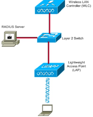
These are the configuration details of the components used in this diagram:
- The IP address of Cisco ISE (RADIUS) server is 10.10.1.24.
- The Management Interface address of the WLC is 10.10.1.17.
- The internal DHCP server on the controller is used to assign the IP address to wireless clients.
- This document uses 802.1x with PEAP as the security mechanism.
- VLAN102 is used throughout this configuration. The username smith -102 is configured to be placed into the VLAN102 by the RADIUS server.
Configuration Steps
This configuration is separated into three categories:
- Cisco ISE Configuration.
- Configure the Switch for Multiple VLANs.
- Catalyst 9800 WLC Configuration.
Cisco ISE Configuration
This configuration requires these steps:
- Configure the Catalyst WLC as an AAA Client on the Cisco ISE Server.
- Configure Internal users on Cisco ISE.
- Configure the RADIUS (IETF) attributes used for dynamic VLAN Assignment on Cisco ISE.
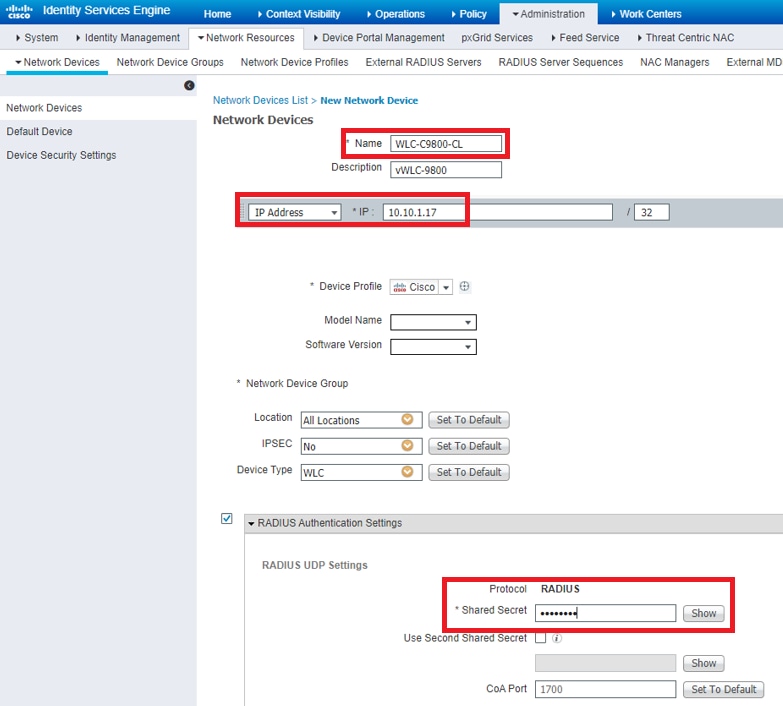
Step 1. Configure the Catalyst WLC as an AAA Client on the Cisco ISE server
This procedure explains how to add the WLC as a AAA client on the ISE server so that the WLC can pass the user credentials to ISE.
Complete these steps:
- From the ISE GUI, navigate to Administration > Network Resources > Network Devices and select Add .
- Complete the configuration with the WLC management IP address and RADIUS shared secret between WLC and ISE as shown in the image:
Step 2. Configure internal users on Cisco ISE
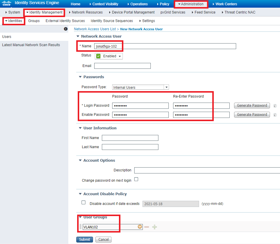
This procedure explains how to add the users on the internal user database of Cisco ISE.
- From the ISE GUI, navigate to Administration > Identity Management > Identities and select Add .
- Complete the configuration with the username, password, and user group as shown in the image:
Step 3. Configure the RADIUS (IETF) attributes used for dynamic VLAN Assignment
This procedure explains how to create an authorization profile and an authentication policy for wireless users.
- From the ISE GUI, navigate to Policy > Policy Elements > Results > Authorization > Authorization profiles and select Add to create a new profile.
- Complete the authorization profile configuration with VLAN information for the respective group. This image shows jonathga-VLAN-102 group configuration settings.
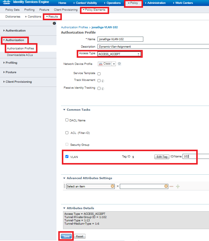
After the authorization profiles are configured, an authentication policy for wireless users needs to be created. You can use a new Custom policy or modify the Default Policy set. In this example, a custom profile is created.
- Navigate to Policy > Policy Sets and select Add to create a new policy as shown in the image:

Now you need to create authorization policies for users in order to assign a respective authorization profile based on group membership.
- Open the Authorization policy section and create policies to accomplish that requirement as shown in the image:

Configure the Switch for Multiple VLANs
To allow multiple VLANs through the switch, you need to issue these commands to configure the switch port connected to the controller:
Note : By default, most of the switches allow all VLANs created on that switch via the trunk port. If a wired network is connected to the switch, then this same configuration can be applied to the switch port that connects to the wired network. This enables the communication between the same VLANs in the wired and wireless network.
Catalyst 9800 WLC Configuration
- Configure the WLC with the Details of the Authentication Server.
- Configure the VLANs.
- Configure the WLANs (SSID).
- Configure the Policy Profile.
- Configure the Policy tag.
- Assign the Policy tag to an AP.
Step 1. Configure the WLC with the Details of the Authentication Server
It is necessary to configure the WLC so it can communicate with the RADIUS server to authenticate the clients.
- From the controller GUI, navigate to Configuration > Security > AAA > Servers / Groups > RADIUS > Servers > + Add and enter the RADIUS server information as shown in the image:
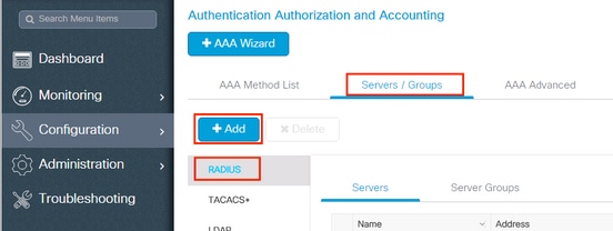
- In order to add the RADIUS server to a RADIUS group, navigate to Configuration > Security > AAA > Servers / Groups > RADIUS > Server Groups > + Add as shown in the image:
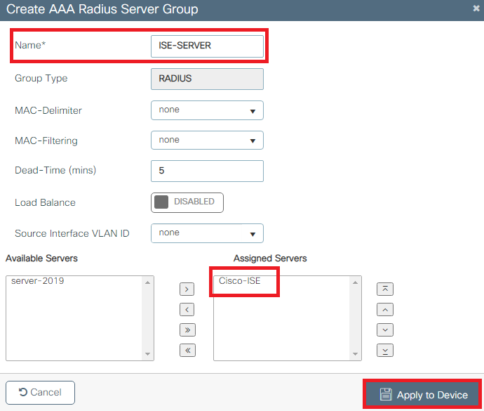
- In order to create an Authentication Method List, navigate to Configuration > Security > AAA > AAA Method List > Authentication > + Add as shown in the images:
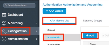
Step 2. Configure the VLANs
This procedure explains how to configure VLANs on the Catalyst 9800 WLC. As explained earlier in this document, the VLAN ID specified under the Tunnel-Private-Group ID attribute of the RADIUS server must also exist in the WLC.
In the example, the user smith-102 is specified with the Tunnel-Private-Group ID of 102 (VLAN =102) on the RADIUS server.
- Navigate to Configuration > Layer2 > VLAN > VLAN > + Add as shown in the image:
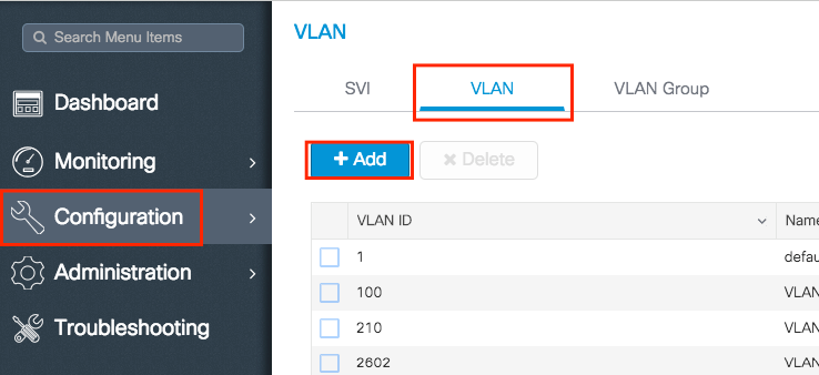
- Enter the needed information as shown in the image:
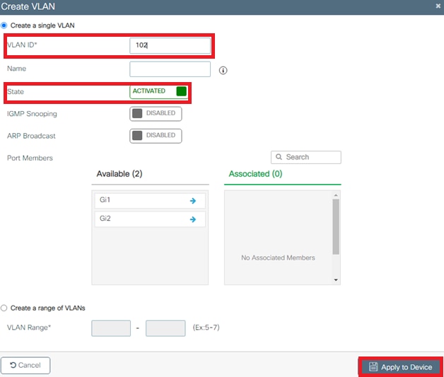
Note : If you do not specify a name, the VLAN automatically gets assigned the name of VLANXXXX, where XXXX is the VLAN ID.
Repeat steps 1 and 2 for all the needed VLANs, once done you can continue to step 3.
- If you have a port channel in use, navigate to Configuration > Interface > Logical > PortChannel name > General . If you see it configured as Allowed VLAN = All you are done with the configuration. If you see Allowed VLAN = VLANs IDs , add the needed VLANs and after that select Update & Apply to Device .
- If you do not have port channel in use, navigate to Configuration > Interface > Ethernet > Interface Name > General . If you see it configured as Allowed VLAN = All you are done with the configuration. If you see Allowed VLAN = VLANs IDs , add the needed VLANs and after that select Update & Apply to Device .
This images show the configuration related to the interface setup if you use All or specific VLAN IDs.
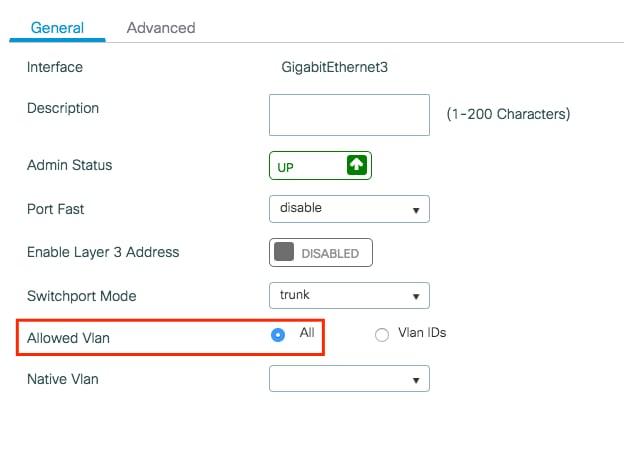
Step 3. Configure the WLANs (SSID)
This procedure explains how to configure the WLANs in the WLC.
- In order to create the WLAN. Navigate to Configuration > Wireless > WLANs > + Add and configure the network as needed, as shown in the image:

- Enter the WLAN information as shown in the image:
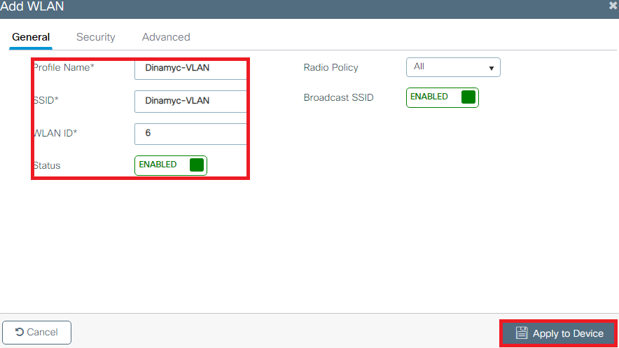
- Navigate to Security tab and select the needed security method. In this case WPA2 + 802.1x as shown in the images:
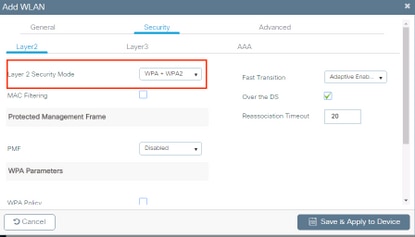
From Security > AAA tab, select the authentication method created on step 3 from Configure the WLC with the Details of the Authentication Server section as shown in the image:
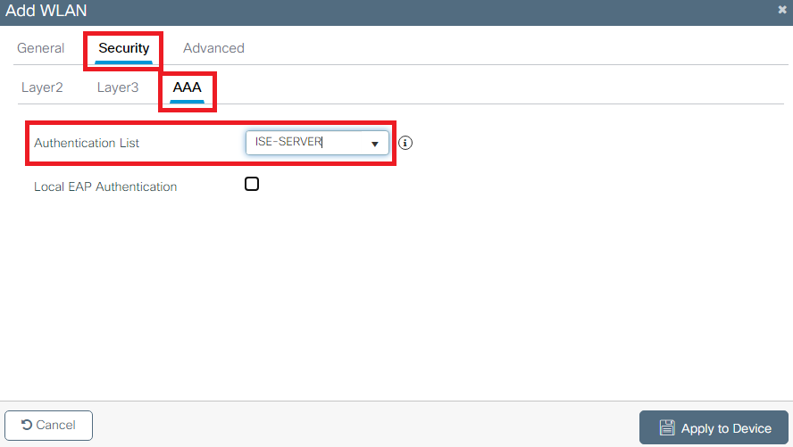
Step 4. Configure the Policy Profile
This procedure explains how to configure the Policy Profile in the WLC.
- Navigate to Configuration > Tags & Profiles > Policy Profile and either configure your default-policy-profile or create a new one as shown in the images:

- From the Access Policies tab assign the VLAN to which the wireless clients are assigned when they connect to this WLAN by default as shown in the image:
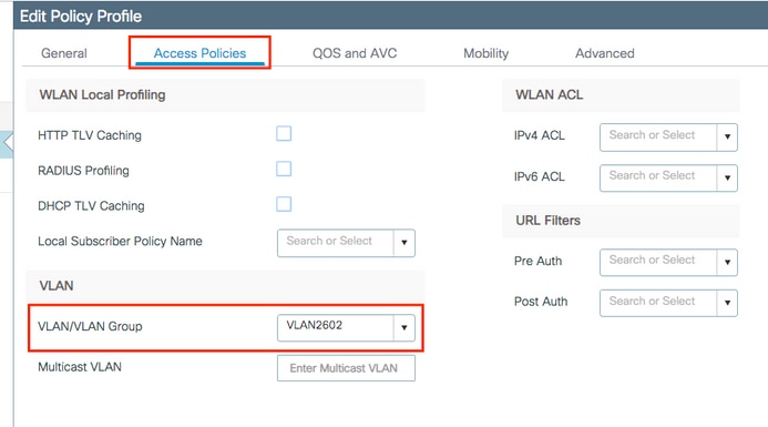
Note : In the example provided, it is the job of the RADIUS server to assign a wireless client to a specific VLAN upon successful authentication, therefore the VLAN configured on the policy profile can be a black hole VLAN, the RADIUS server overrides this mapping and assigns the user that comes through that WLAN to the VLAN specified under the user Tunnel-Group-Private-ID field in the RADIUS server.
- From the Advance tab, enable the Allow AAA Override check box to override the WLC configuration when the RADIUS server returns the attributes needed to place the client on the proper VLAN as shown in the image:
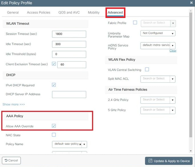
Step 5. Configure the Policy Tag
This procedure explains how to configure the Policy tag in the WLC.
- Navigate to Configuration > Tags & Profiles > Tags > Policy and add a new one if needed as shown in the image:
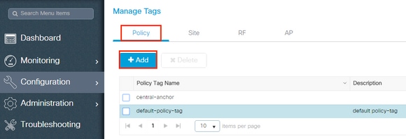
- Add a name to the Policy Tag and select +Add , as shown in the image:
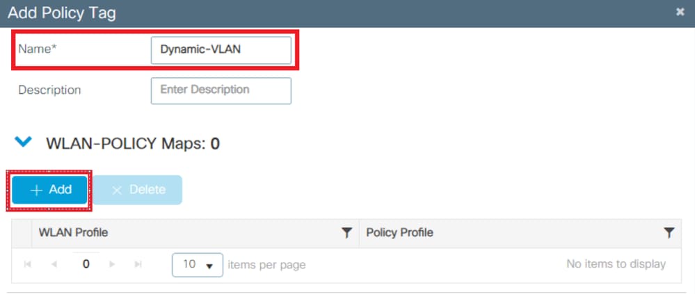
- Link your WLAN Profile to the desired Policy Profile as shown in the images:
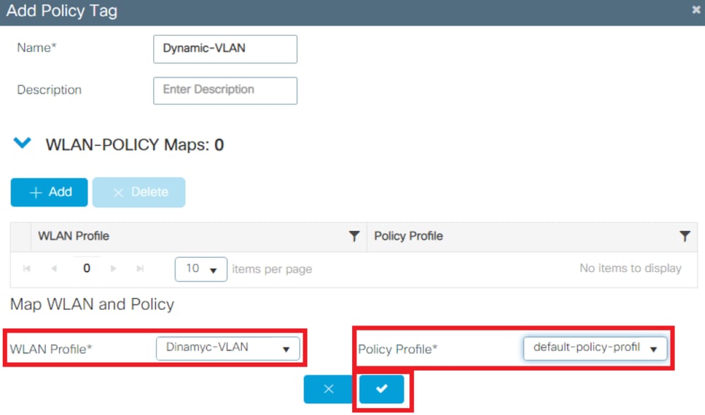
Step 6. Assign the Policy Tag to an AP
- Navigate to Configuration > Wireless > Access Points > AP Name > General Tags and assign the relevant policy tag and then select Update & Apply to Device as shown in the image:
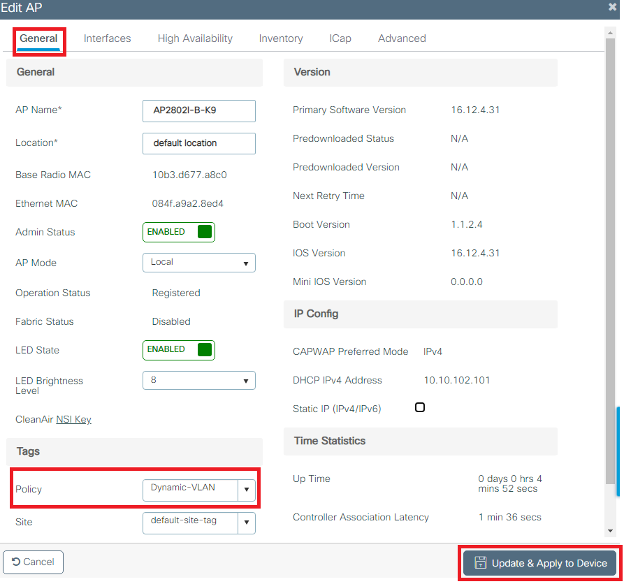
Caution : Be aware that changing the policy tag on an AP results in the AP disconnecting from the WLC and then reconnecting.
Flexconnect
The Flexconnect feature allows APs to send wireless client data to egress through the AP LAN port when configured as a trunk. This mode, known as Flexconnect Local Switching, allows the AP to segregate client traffic by tagging it in separate VLANs from its management interface. This section provides instructions on how to configure Dynamic VLAN assignment for the local switching scenario.
Note : The steps outlined in the previous section are applicable to the Flexconnect scenario as well. To complete the configuration for Flexconnect, please do the additional steps provided in this section.
To allow multiple VLANs through the switch, you need to issue the next commands to configure the switch port connected to the AP:
- Switch(config-if)# switchport mode trunk
- Switch(config-if)# switchport trunk encapsulation dot1q
Note : By default, most of the switches allow all VLANs created on the switch via the trunk port.
Flexconnect Policy Profile configuration
- Navigate to Configuration > Tags & Profiles > Policy Profile > +Add and create a new policy.
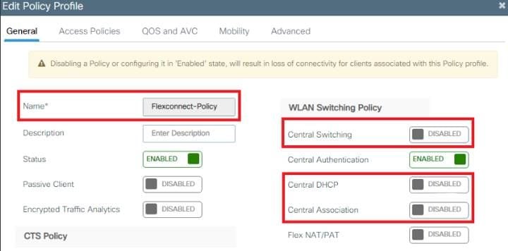
Note : Starting with the 17.9.x code, the policy-profile appearance has been updated as depicted in the picture.
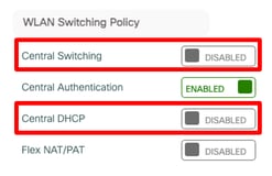
Note : The VLAN configured on this step is not required to be present on the VLAN list of the WLC. Necessary VLANs are added on the Flex-Profile later, which creates the VLANs on the AP itself.
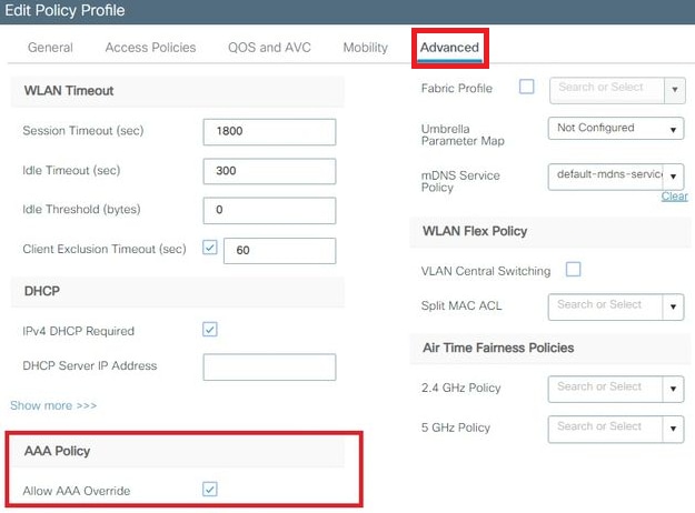
Assign the Flexconnect policy profile to a WLAN and Policy tag
Note : A Policy Tag is used to link the WLAN with the Policy Profile. You can either create a new Policy Tag or use the default-policy tag.
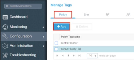
- Click on the Apply to Device button.
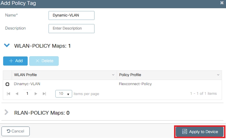
Configure the Flex Profile
To dynamically assign a VLAN ID via RADIUS on a FlexConnect AP, it is necessary for the VLAN ID mentioned in the Tunnel-Private-Group ID attribute of the RADIUS response to be present on the access points. The VLANs are configured on the Flex profile.
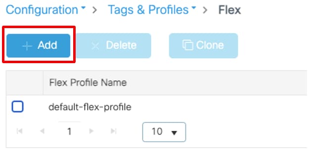
Note : The native VLAN ID refers management VLAN for the AP, so it must match the native VLAN configuration of the switch the AP is connected to
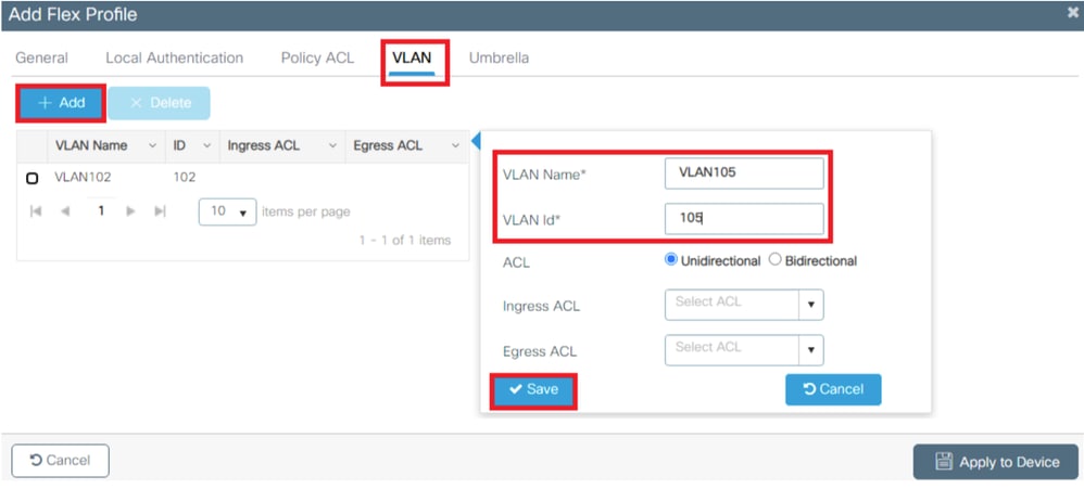
Note : In step 3 of the section Flexconnect Policy Profile Configuration, you configured the default VLAN assigned to the SSID. If you use a VLAN name on that step, ensure that you use the same VLAN name on the Flex Profile configuration, otherwise, clients are not able to connect to the WLAN.
Flex Site tag configuration
- Navigate to Configuration > Tags & Profiles > Tags > Site > +Add, to create a new site tag .
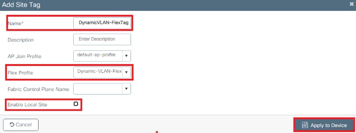
Assign the Policy and Site Tag to an AP.
- Navigate to Configuration > Wireless > Access Points > AP Name > General Tags, assign the relevant policy and site tag and then click Update & Apply to Device.
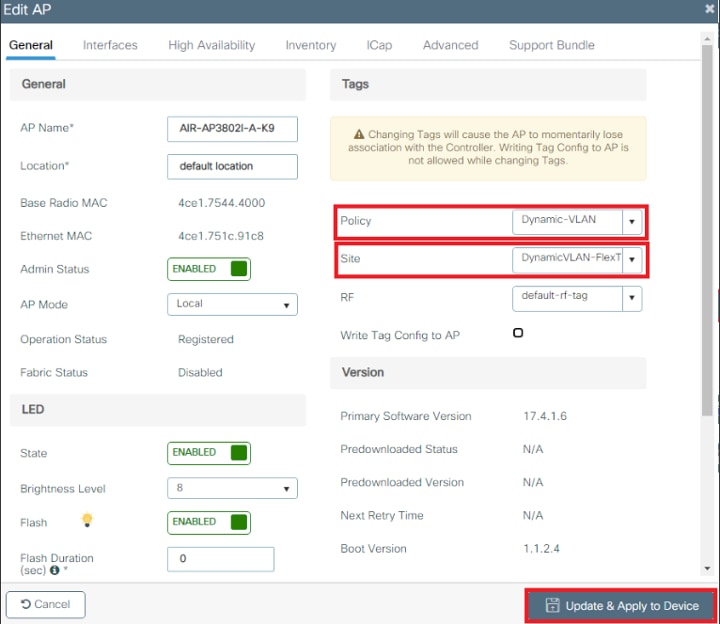
Caution : Be aware that changing the policy and site tag on an AP results in the AP disconnecting from the WLC and then reconnecting.
Note : If the AP is configured in Local mode (or any other mode) and then it gets a Site Tag with the "Enable Local Site" setting disabled, the AP reboots and comes back in FlexConnect mode
Use this section to confirm that your configuration works properly.
Configure the test client SSID profile using the proper EAP protocol and credentials defined in ISE that can return a Dynamic VLAN assignment. Once you are prompted for a username and password, enter the information of the user mapped to a VLAN on ISE.
In the previous example, notice that smith-102 is assigned to the VLAN102 as specified in the RADIUS server. This example uses this username to receive authentication and to be assigned to a VLAN by the RADIUS server:
Once the authentication is completed, you need to verify that your client is assigned to the proper VLAN as per the RADIUS attributes sent. Complete these steps to accomplish this task:
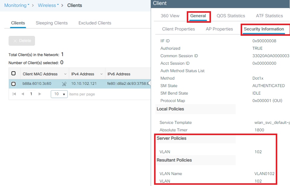
From this window, you can observe that this client is assigned to VLAN102 as per the RADIUS attributes configured on the RADIUS server.
From the CLI you can use the show wireless client summary detail to view the same information as shown in the image:
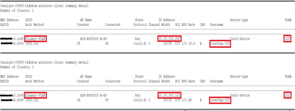
- From the controller GUI, navigate to Troubleshooting > Radioactive Trace > +Add .
- Enter the Mac Address of the wireless client.
- Select Start .
- Connect the client with the WLAN.
- Navigate to Stop > Generate > Choose 10 minutes > Apply to Device > Select the trace file to download the log .
This portion of the trace output ensures a successful transmission of RADIUS attributes:
Troubleshoot
There is currently no specific troubleshooting information available for this configuration.
Related Information
- End User Guide
- Cisco Technical Support & Downloads
Revision History
| Revision | Publish Date | Comments |
|---|---|---|
Contributed by Cisco Engineers
- Jonathan de Jesus Garcia Cisco TAC Engineer
- Jose Pablo Munoz Cisco TAC Engineer
Was this Document Helpful?

Contact Cisco
- (Requires a Cisco Service Contract )
This Document Applies to These Products
- Wireless LAN Controller Software
A Platform for Software Engineers
Limited Time Offer!
For Less Than the Cost of a Starbucks Coffee, Access All DevOpsSchool Videos on YouTube Unlimitedly. Master DevOps, SRE, DevSecOps Skills!
Incorrect VLAN assignment
scmuser created the topic: Incorrect VLAN assignment
Symptom: When installing new services on the network such as wireless or VoIP, VLANs are typically used to isolate this traffic from other users. This requires each switch port supporting these services to be configured for the proper VLAN. If this is not done properly, the service may not work. The IP Phone may not register with the call manager, the PC connected to the phone may not be able to connect to key servers, or the wireless users may not get proper addressing for the wireless environment.
sgadmin replied the topic: Re:Incorrect VLAN assignment
Cause: The switches responsible for connecting these services have not been properly configured. Perhaps it was not communicated within the organization to reconfigure certain ports to support new services. Resolution: Test the port to verify which VLANs are supported. If possible, use a VLAN Tag to generate VLAN specific traffic to check which VLANs are configured on the port. Check the IP address provided by the DHCP server to determine which VLAN is being provided to the port if it is untagged. Alternatively, check the switch configuration to validate the VLAN configuration.
- Recent Posts
- Use of runtime variables to save into another variable using register in Ansible - September 6, 2018
- Ansible & Ansible Tower Variable Precedence Hierarchy - September 6, 2018
- How to use template in Ansible? - September 6, 2018

IMAGES
VIDEO
COMMENTS
An incorrect configuration could result from a typo in the configuration process or a wrong VLAN ID configuration on the endpoint's switch interface, which puts it in the wrong VLAN/subnet. Observe the symptoms, and determine if the problem is at the physical layer, data link layer, routed layer or application layer.
VLAN configuration issues can be challenging to troubleshoot. You can't see the VLAN on your local device. All of the VLAN configurations are done on the switch. Every interface on the switch is assigned to a VLAN, and if you're connecting to an interface that is assigned to the wrong VLAN, you may run into problems.
The best way to prevent incorrect VLAN assignments is by maintaining proper documentation, but in a dynamic environment with a lot of moves, adds, and changes, it's quite possible that a user or device ends up on the wrong switch port and therefore the wrong VLAN.
Some of the common VLAN issues include: 1. VLAN Connectivity Problems. Connectivity problems can arise when devices within a VLAN are unable to communicate with each other or with devices in other VLANs. This can result from misconfigured VLAN trunks, incorrect VLAN assignments, or issues with the network switch.
Additionally, ensure the trunk links between switches are configured to allow the respective VLANs. Incorrect VLAN Assignment. Devices might end up on the wrong VLAN due to incorrect port configurations. This problem is commonly solved by double-checking the access mode VLAN settings on individual ports. Ensure that each port is assigned to the ...
Troubleshooting Incorrect VLANs. VLANs provide a method of segmenting and organizing the network. Computer systems can be located anywhere on the network but communicate as if they are on the same segment. ... In static VLAN assignment, the switch ports are assigned to a specific VLAN, and new systems added will be assigned to the VLAN ...
VLAN assignment issues. Here is the topology: H1 is unable to ping H2. There are no issues with the hosts, the problem is related to the switch. ... Something is wrong with the interface. We proved this wrong because it shows up/up so it seems to be active. The interface is not an access port but a trunk.
VLAN issues constitute a local area network problem. An obvious symptom is your local server being unable to reach other hosts on the same local network, such as your default gateway. Take a look at an example: # ping 192.168.1.254. PING 192.168.1.254 (192.168.1.254) 56 (84) bytes of data.
Check for Incorrect VLAN Assignments: Use the show vlan or show running-config command to ensure all ports are correctly assigned to their respective VLANs. Verify Trunk Configurations: Misconfigured trunk ports can prevent VLANs from communicating properly. Verify trunk settings with the show interfaces trunk command.
scmuser created the topic: Incorrect VLAN assignment. Symptom: When installing new services on the network such as wireless or VoIP, VLANs are typically used to isolate this traffic from other users. This requires each switch port supporting these services to be configured for the proper VLAN. If this is not done properly, the service may not work.
Assign port Fa0/6 to VLAN 10 and verify the port assignment, as shown in Example 4-34. ... For instance, an incorrect IP address was configured or the wrong VLAN ID was assigned to the subinterface. For example, R1 should be providing inter-VLAN routing for users in VLANs 10, 20, and 99. However, users in VLAN 10 cannot reach any other VLAN.
Traffic loops: Traffic loops are one of the most common causes of a slow VLAN. The traffic from one switch to another gets looped, thereby overloading the traffic. The ...
As shown in Figure 3-25, use the show vlan command to check whether the port belongs to the expected VLAN. If the port is assigned to the wrong VLAN, use the switchport access vlan command to correct the VLAN membership on a particular port. Use the show mac address-table command to check which addresses were learned on a particular port of the switch and to which VLAN that port is assigned ...
The assignment of VLANs are (from lowest to highest precedence): 1. The default VLAN is the VLAN configured for the WLAN (see Virtual AP Profiles). 2. Before client authentication, the VLAN can be derived from rules based on client attributes (SSID, BSSID, client MAC, location, and encryption type).
On Layer 2 switches, it can be. Symptom. VLAN is created on the switch but in a down state. Solution. Execute the show vlan command. If it shows "down," make sure there's at least one port ...
When the switch is configured with an IP address on any VLAN, the 'fallback' IP address on VLAN1 (192.168.1.254) will be released.To preserve connectivity, prior to assigning an IP address to any VLAN interface, ensure the management VLAN has an IP address assigned first. The IP address can be obtained via a DHCP server or statically assigned to the VLAN interface. This article provides ...
Complete these steps: From the ISE GUI, navigate to Administration > Identity Management > Identities and select Add. Complete the configuration with the username, password, and user group as shown in the image: Step 3. Configure the RADIUS (IETF) attributes used for dynamic VLAN Assignment.
scmuser created the topic: Incorrect VLAN assignment Symptom: When installing new services on the network such as wireless or VoIP, VLANs are typically used to isolate this traffic from other users. This requires each switch port supporting these services to be configured for the proper VLAN. If this is not done properly, the service may […]
Incorrect VLAN assignment. A user reports that network access from her workstation is very slow. The problem does not seem to be affecting any other ways. Which of the following conditions is the most likely cause? Duplex mismatch. You manage a network with multiple switches. You find that your switches are experiencing heavy broadcast storms.